Parameter Characteristic Application Videos
Product Introduction
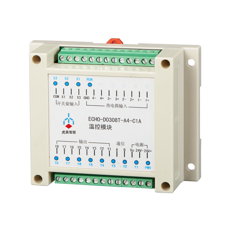
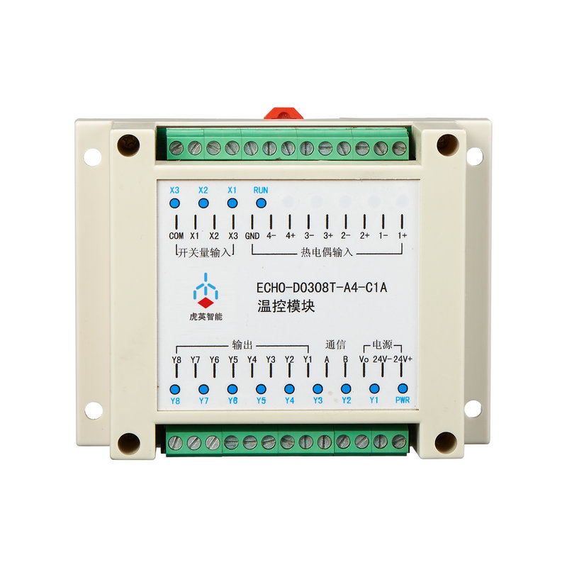
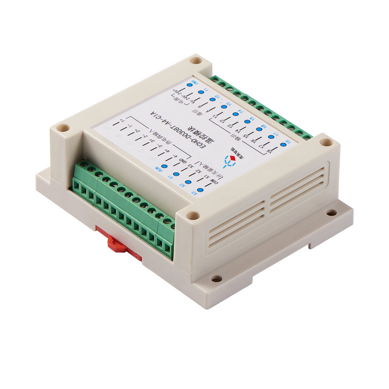
Temperature control module (ECHO-D0308T-A4-C1A) temperature control module is the latest temperature control module developed by our company, which integrates a microcontroller and a temperature controller. Temperature control can also be achieved without a PLC for the user. This greatly reduces user usage costs. This module integrates 3 channels of switch input, 4 channels of temperature acquisition, and 8 channels of transistor switch output (4 channels are used for temperature control output, and the other 4 channels can be freely output). It has multiple control methods such as PID, manual output, and upper computer control. It can be used in various places that require temperature control, especially suitable for integrating control systems with PLC and touch screens. Three switch signals can be used as free inputs, four temperature acquisition signals can be connected to thermocouples or thermal resistance temperature sensors, and four switch signal outputs drive transistors in PWM mode. External relays are connected to continuously conduct and disconnect the heating device through the relay, thereby achieving temperature control. The other 4 channels can be controlled by the upper computer for free output. The temperature control module is connected to other devices through the RS485 bus and supports the MODBUS-RTU communication protocol.
Product characteristics and technical indicators
1、Using a 32-bit MCU processor and a 16 bit ∑ - ∆ AD analog-to-digital conversion chip;
2、It has multiple control methods, including PID control, manual control, and upper computer control;
3、Use DC isolated power supply with isolated RS485 communication. Has good anti-interference ability;
4、Built in cold end compensation;
5、Sensor: Supports K, J, E, T-type thermocouples and PT100
6、3-way switch input, 4-way temperature acquisition, 4-way temperature control, 4-way switch output
7、Resolution: 0.1 ° C, accuracy: ± 0.2 ° C
8、Cold end compensation error:<±2°C
9、Switching output: 8 channels of switching output, with a maximum current of 200mA per channel
10、Communication interface:RS485
11、DC24V power supply, local power consumption<3W
12、Environmental temperature: 0°C~60°C,Relative humidity:<85% without condensation.
External dimensions
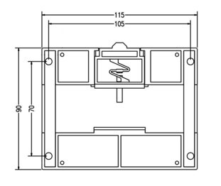
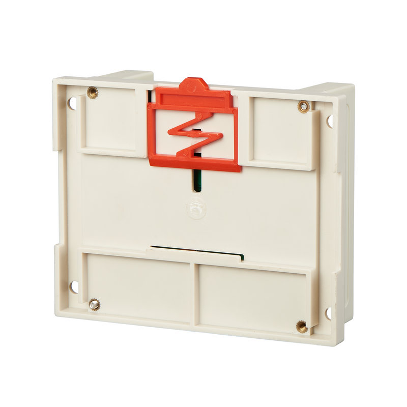
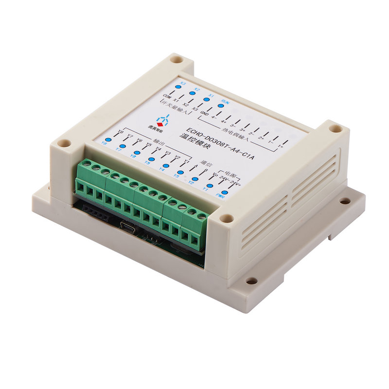
The external dimensions are 115 * 90 * 40mm, and the module can be installed on industrial standard rails; The module can also be installed on other workbenches through fixed holes with a diameter of 5mm on both sides.
Wiring method and instructions
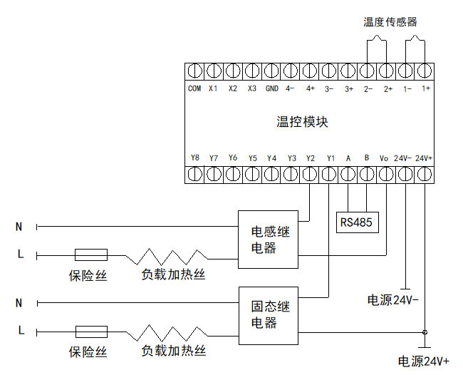
After the module is powered on, the power indicator light is on and the operation indicator light is flashing.
1、The X1, X2, and X3 indicator lights correspond to three free switching inputs respectively;
2、Y1,Y2,Y3,Y4,Y5,Y6,Y7,Y8 The indicator lights correspond to 4 temperature control outputs and 4 free outputs respectively;
3、There are different wiring methods for connecting 4 temperature control outputs to resistive loads (such as solid-state relays) or inductive loads (electromagnetic relays). Please refer to the wiring diagram. Vo is an internally connected rectifier diode with a 24V output.
4、The positive and negative terminals of the thermocouple need to be correctly connected according to the silk screen indication on the temperature control module. 1+represents the first positive pole, and 1- represents the first negative pole;
5、Proper grounding can prevent interference from common mode voltage. Excessive common mode voltage can cause measurement errors or unstable measurement data in the module, and even damage the module. According to different types of thermocouples, there are two grounding methods: shielding layer grounding and thermocouple negative terminal grounding.
Shielding layer grounding is the process of connecting the shielding layer of four thermocouples with wires to the analog ground terminal of the module. This grounding method is used for grounding type thermocouples. A grounded thermocouple refers to a thermocouple whose shielding layer is connected to the positive and negative terminals of the thermocouple (with low resistance, usually only a few ohms).
The negative terminal grounding of thermocouples refers to connecting the negative terminals (1- to 4-) of four thermocouples with wires to the analog ground terminal of the module. This grounding method is used for non grounded thermocouples. This type of thermocouple refers to a thermocouple whose shielding layer is not connected to the positive and negative terminals of the thermocouple. There is no shielding layer and the thermocouples are insulated from each other (measure the resistance between each thermocouple with a multimeter to infinity), and the grounding method is also changed.
Product features
1、Adopting a 32-bit MCU processor and a 16 bit ∑ - ∆ AD digital to analog conversion chip;
2、It has multiple control methods, including PID control, manual control, and upper computer control;
3、Use DC isolated power supply with isolated RS485 communication. Has good anti-interference ability;
4、Built in cold end compensation;
5、Sensor: Supports K, J, E, T-type thermocouples and PT100
6、3 channels of switching input, 4-way temperature acquisition, 4-way temperature control, 4-way switch output
7、Resolution: 0.1 ° C, accuracy: ± 0.2 °C
8、Cold end compensation error:<±2°C
9、Switch output: 8 switch outputs, maximum current per channel 200mA
10、communication interface :RS485
11、DC24V power supply, local power consumption<3W
12、Environmental temperature: 0 ° C~60 ° C, relative humidity:<85% without condensation.
 English
 Chinese

